Table of Contents >> Show >> Hide
- What Is an Oscilloscope?
- Before You Start: Know the Main Controls
- Safety First: The Probe Is Not Just a Pointy Wire
- 1. Use the Oscilloscope to View Waveform Shape
- 2. Use the Oscilloscope to Measure Voltage, Frequency, and Timing
- 3. Use the Oscilloscope to Compare Two or More Signals
- 4. Use the Oscilloscope to Troubleshoot Problems
- Choosing the Right Probe and Settings
- Bandwidth and Sample Rate: Why They Matter
- Common Oscilloscope Mistakes to Avoid
- Practical Experience Notes: What Using an Oscilloscope Feels Like in the Real World
- Conclusion
An oscilloscope is the closest thing electronics has to a truth serum. A multimeter can tell you that a circuit has 5 volts, but an oscilloscope shows what those 5 volts are actually doing over time: rising, falling, puto be “basically finished.”
Whether you are learning electronics, debugging a sensor, checking a PWM signal, testing an audio circuit, or wondering why a microcontroller refuses to behave like the polite little chip it promised to be, knowing how to use an oscilloscope gives you a powerful advantage. Instead of guessing, you can see the signal. Instead of replacing random parts, you can measure the problem. Instead of saying “it should work,” you can finally ask, “what is it actually doing?”
This guide explains four practical ways to use the oscilloscope: viewing waveforms, measuring signals, comparing timing between circuits, and troubleshooting real-world electrical problems. Along the way, you will learn the key oscilloscope controls, how probes work, how triggering stabilizes the display, and what to watch out for when measuring circuits safely.
What Is an Oscilloscope?
An oscilloscope, often called a scope, is an electronic test instrument that displays voltage as it changes over time. On the screen, the vertical axis represents voltage, while the horizontal axis represents time. That simple idea unlocks a lot of diagnostic power. You can see a signal’s amplitude, frequency, shape, noise, timing, duty cycle, and unexpected behavior all in one place.
Most modern oscilloscopes are digital storage oscilloscopes. They sample the input signal, convert it into digital data, and draw the waveform on a screen. Many scopes also offer automatic measurements, cursors, math functions, protocol decoding, memory capture, and single-shot triggering. In plain English: they do a lot more than draw squiggly lines, although the squiggly lines are still the fun part.
Before You Start: Know the Main Controls
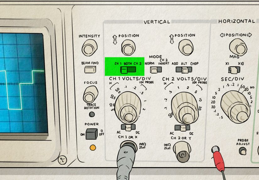
The front panel of an oscilloscope may look like someone spilled a bag of knobs onto a spaceship dashboard, but the controls usually fall into three friendly groups: vertical, horizontal, and trigger.
Vertical Controls
Vertical controls adjust how tall the waveform appears. The most important setting is volts per division. If the waveform is tiny, lower the volts-per-division setting. If it flies off the screen like an overexcited squirrel, increase it. Vertical position moves the waveform up or down, and channel controls let you choose which input is displayed.
Horizontal Controls
Horizontal controls adjust the time scale. The time-per-division setting determines how much time is shown across the screen. A slow signal might need milliseconds or seconds per division, while a fast digital signal may need microseconds or nanoseconds per division. Horizontal position shifts the waveform left or right so you can inspect the part you care about.
Trigger Controls
The trigger tells the oscilloscope when to begin drawing the waveform. Without a proper trigger, a repeating signal may slide, jitter, or roll across the display. With the right trigger level and slope, the waveform locks into place. Triggering is the difference between “beautiful diagnostic display” and “electrical spaghetti screensaver.”
Safety First: The Probe Is Not Just a Pointy Wire
Oscilloscope safety starts with understanding the probe and ground clip. On many bench oscilloscopes, the probe ground clip is connected to earth ground through the instrument’s power cord. That means clipping it to the wrong point in a live circuit can create a short circuit. For low-voltage DC electronics, this is usually straightforward: connect the ground clip to circuit ground and the probe tip to the test point. For mains-powered or high-voltage equipment, use the correct safety-rated probe, isolation method, or differential probe, and do not improvise.
A common beginner mistake is using the oscilloscope like a multimeter, moving the ground clip around wherever convenient. Please do not. The ground clip is not a floating reference on a standard earth-grounded scope. When in doubt, stop and verify the measurement setup before touching the circuit.
1. Use the Oscilloscope to View Waveform Shape
The first and most fundamental way to use an oscilloscope is to view the shape of an electrical signal. This is where the instrument shines. A voltage reading alone cannot tell you whether a signal is a clean sine wave, a square wave, a triangle wave, a noisy pulse train, or something that looks like it escaped from a haunted radio.
To view a waveform, connect the probe ground clip to the circuit ground, place the probe tip on the signal point, select the correct input channel, and adjust the vertical and horizontal scales until the waveform fits comfortably on the screen. If your scope has an Auto Set button, it can be helpful for a first look. However, do not rely on Auto Set forever. It is useful, but it is not magic. Learning to adjust volts per division, time per division, and trigger level manually will make you much better at diagnosing real problems.
Example: Checking a Square Wave
Suppose you are testing a microcontroller output pin that should be producing a 1 kHz square wave. On a multimeter, you might see an average voltage that does not tell the full story. On an oscilloscope, you can see whether the signal actually switches between low and high levels, how fast the edges rise, whether the duty cycle is correct, and whether noise appears on the transitions.
If the square wave has rounded corners, the circuit may be bandwidth-limited, overloaded, or measured with a probe setup that is affecting the signal. If you see overshoot or ringing, the problem may involve layout, grounding, long probe leads, impedance mismatch, or fast edge rates. In other words, the oscilloscope does not just say “there is a signal.” It says, “Here is the signal, and by the way, it has opinions.”
Common Waveform Shapes
A sine wave often appears in audio, radio-frequency, and AC test signals. A square wave is common in digital electronics, clock lines, and PWM outputs. A triangle or sawtooth wave may appear in timing circuits, ramp generators, motor controls, or waveform generators. Random-looking noise may come from switching supplies, poor grounding, interference, or unstable circuits. Recognizing these patterns helps you understand what the circuit is doing without needing to decode every component on the board.
2. Use the Oscilloscope to Measure Voltage, Frequency, and Timing
The second major way to use the oscilloscope is measurement. Once the waveform is stable on the screen, you can measure voltage levels, frequency, period, pulse width, rise time, fall time, duty cycle, and more. Many digital oscilloscopes include automatic measurement tools, but manual measurement with divisions and cursors is still valuable because it teaches you what the numbers mean.
Measuring Voltage
Voltage is measured vertically. If the vertical scale is set to 1 volt per division and the waveform is three divisions tall from bottom to top, the peak-to-peak voltage is about 3 volts. Many scopes can calculate peak-to-peak voltage, RMS voltage, maximum voltage, minimum voltage, and average voltage automatically.
Peak-to-peak voltage is especially useful when looking at waveforms such as audio signals, ripple on a power rail, or digital pulses. For example, a 5 V logic signal should typically swing close to 0 V and 5 V. If the high level only reaches 2.7 V, the receiving device may not recognize it correctly, depending on the logic family and threshold requirements.
Measuring Frequency and Period
Frequency and period are measured horizontally. Period is the time it takes for one full cycle of a repeating waveform. Frequency is the number of cycles per second. If one cycle takes 1 millisecond, the frequency is 1,000 cycles per second, or 1 kHz.
On the oscilloscope, count the horizontal divisions for one complete cycle and multiply by the time-per-division setting. For instance, if one cycle spans five divisions and the scope is set to 200 microseconds per division, the period is 1 millisecond. That means the frequency is 1 kHz. Congratulations: you have just done math with a purpose, which is the best kind of math.
Measuring Duty Cycle
Duty cycle tells you what percentage of a repeating signal is in the “on” state. This matters in PWM motor control, LED dimming, switching regulators, and digital communication. A PWM signal with a 25% duty cycle is high for one quarter of each cycle and low for the remaining three quarters. A 75% duty cycle stays high much longer.
To measure duty cycle manually, compare the high-time of the pulse to the full period. Many oscilloscopes can display duty cycle automatically, but checking it visually is a great habit. If an LED dimmer looks wrong, a fan spins too slowly, or a motor controller acts strange, duty cycle is one of the first measurements worth checking.
3. Use the Oscilloscope to Compare Two or More Signals
The third way to use an oscilloscope is comparing signals. Many scopes have two or four channels, which lets you view multiple waveforms at the same time. This is extremely helpful when you need to understand timing relationships between different parts of a circuit.
Example: Input vs. Output
Imagine you are testing an amplifier. Channel 1 can measure the input signal, while Channel 2 measures the output. By comparing them, you can see whether the output is larger, smaller, delayed, distorted, clipped, or inverted. If the input is a clean sine wave but the output has flattened peaks, the amplifier may be clipping. If the output is noisy, the power supply, grounding, or layout may need attention.
Example: Clock and Data Lines
In digital electronics, comparing signals is essential. A microcontroller may use one line for a clock and another for data. With two oscilloscope channels, you can see whether the data changes at the correct time relative to the clock. If the timing is off, the circuit may fail even though each signal looks acceptable by itself.
This is why oscilloscopes are so useful in debugging communication problems. A logic analyzer is excellent for decoding digital states, but an oscilloscope shows the analog reality underneath: voltage levels, ringing, slow edges, overshoot, undershoot, and noise. Digital circuits may speak in ones and zeros, but the wires still live in the analog world.
Checking Phase Difference
Oscilloscopes can also compare phase between two periodic signals. Phase describes how far one waveform is shifted relative to another. This is useful in audio circuits, filters, AC systems, power electronics, and control circuits. If two sine waves have the same frequency but one reaches its peak later, the oscilloscope can show that delay clearly.
4. Use the Oscilloscope to Troubleshoot Problems
The fourth and perhaps most satisfying way to use an oscilloscope is troubleshooting. This is where the scope becomes less like a measurement tool and more like a detective with a glowing screen. It helps you find intermittent glitches, power supply ripple, unstable oscillations, missing signals, poor grounding, communication errors, and timing issues that would otherwise hide from simpler tools.
Troubleshooting Power Supply Ripple
A DC power supply should ideally be steady, but real power rails often contain ripple, noise, or switching spikes. Set the oscilloscope input coupling to AC when you want to zoom in on small ripple riding on top of a DC voltage. For example, a 5 V power rail may look fine on a multimeter, but the oscilloscope might reveal 200 mV of ripple or sharp spikes that cause a microcontroller to reset.
When measuring small noise, keep the probe ground lead short. Long ground leads can act like tiny antennas and add ringing that is not really present in the circuit. This is one of those oscilloscope lessons that feels unfair at first: sometimes the weird waveform is not the circuit’s fault; it is your measurement setup wearing a fake mustache.
Finding Glitches and Intermittent Events
Some circuit problems happen too quickly or too rarely to catch with a normal display. That is where triggering and single-shot capture become valuable. A scope can be set to trigger when a signal crosses a certain voltage, produces a narrow pulse, drops below a threshold, or behaves in a specific way. Once triggered, the scope captures the event so you can inspect it.
For instance, if a sensor line occasionally drops for a few microseconds, the device may malfunction even though the signal looks normal most of the time. A single capture or glitch trigger can catch the brief event. Without an oscilloscope, you might blame the software, the sensor, the weather, the moon phase, and possibly your chair.
Debugging PWM and Motor Control
Pulse-width modulation is common in motor drivers, LED dimmers, heaters, and switching converters. An oscilloscope lets you verify PWM frequency, duty cycle, voltage level, edge quality, and timing. If a motor whines, an LED flickers, or a driver runs hot, the waveform may reveal whether the control signal is correct.
A PWM waveform that looks clean at the microcontroller pin may look very different at the gate of a transistor or across a load. Comparing those points can reveal weak drive strength, excessive capacitance, poor layout, or switching noise. The oscilloscope gives you a map of how the signal changes as it moves through the circuit.
Choosing the Right Probe and Settings
A good measurement depends on the probe as much as the oscilloscope. Passive probes are common, affordable, and useful for general electronics work. Many have 1x and 10x settings. A 10x probe reduces the signal amplitude going into the scope, but it also usually reduces circuit loading and improves bandwidth. For many digital and high-frequency measurements, 10x mode is the better choice.
Probe compensation matters too. Many scopes include a built-in square wave output for probe adjustment. If a compensated probe shows a square wave with rounded edges or excessive overshoot, adjust the compensation until the square wave looks flat and square. It is a small step, but it prevents misleading measurements.
Bandwidth and Sample Rate: Why They Matter
Oscilloscope bandwidth determines the range of frequencies the scope can measure accurately. A common rule of thumb is to use a scope and probe with several times more bandwidth than the highest-frequency signal or fastest edge you need to observe. For digital signals, edge speed can matter more than the basic clock frequency because fast transitions contain high-frequency content.
Sample rate determines how many times per second the oscilloscope digitizes the signal. Higher sample rates provide more detail, especially for fast-changing waveforms. If the sample rate is too low, the displayed waveform may be inaccurate or misleading. In practical terms, bandwidth helps the scope “see” the signal, while sample rate helps it “draw” the signal clearly.
Common Oscilloscope Mistakes to Avoid
Using the Wrong Ground Point
Always confirm where circuit ground is before attaching the probe ground clip. On low-voltage DC circuits, this is usually simple. On mains-connected or isolated systems, it can be dangerous if misunderstood. Use the right probe and method for the job.
Forgetting Probe Attenuation Settings
If the probe is set to 10x but the oscilloscope channel is set to 1x, the voltage reading will be wrong by a factor of ten. That is not a tiny rounding error. That is the kind of error that makes a 5 V signal look like 0.5 V and sends you chasing imaginary problems around the workbench.
Relying Too Much on Auto Set
Auto Set is useful for getting started, but it can choose settings that hide important details. Learn to manually adjust volts per division, time per division, coupling, trigger level, and trigger slope. The more comfortable you become with manual controls, the faster you will solve real problems.
Ignoring Measurement Loading
Every probe affects the circuit a little. In sensitive or high-frequency circuits, that effect can matter. Use the proper probe, keep leads short, and avoid assuming that the displayed waveform is perfect truth. It is truth filtered through your measurement setup.
Practical Experience Notes: What Using an Oscilloscope Feels Like in the Real World
The first time you use an oscilloscope, it can feel like you are learning to fly a small airplane made entirely of knobs. There is a channel button, a trigger knob, a time scale, a voltage scale, coupling options, probe settings, menus, measurements, cursors, and usually at least one button you press by accident that makes everything disappear. The good news is that most oscilloscope confusion comes from three simple questions: how tall is the signal, how fast is it changing, and where should the scope start drawing?
One practical habit that helps immediately is starting with a known signal. Many oscilloscopes have a built-in calibration output, often a square wave. Connect your probe to that first. Adjust the vertical scale until the waveform fills a comfortable amount of the screen. Adjust the horizontal scale until you can see a few cycles. Then adjust the trigger level until the waveform stops moving. This short exercise teaches more than staring at the manual while whispering, “Why are there so many buttons?”
Another real-world lesson is that the probe ground lead matters more than beginners expect. A long ground lead may be fine for slow signals, but fast digital edges can look messy because the lead adds inductance. You may see ringing and assume the circuit is terrible, when the measurement setup is partly responsible. Shorter ground connections, spring ground tips, and careful probing can dramatically improve what you see.
Experience also teaches you not to trust one measurement point too much. If a circuit is misbehaving, measure the signal at the source, then at the destination, then at important points in between. For example, a PWM signal might look perfect at the microcontroller pin but distorted at the MOSFET gate. A sensor output might be clean near the sensor but noisy at the controller input. The oscilloscope helps you follow the signal like a trail of breadcrumbs, except the breadcrumbs are voltage and the birds are electromagnetic interference.
In many repairs, the oscilloscope turns vague symptoms into visible evidence. A device that randomly resets may reveal power rail dips. A noisy audio circuit may show hum or oscillation. A serial communication line may show rounded edges or incorrect voltage levels. A switching regulator may show ripple that is larger than expected. These discoveries save time because they replace guessing with observation.
The best mindset is to treat the oscilloscope as a learning partner, not just a repair tool. Even when a circuit works, look at it. Check the power rail, clock line, reset pin, PWM output, amplifier input, and amplifier output. Over time, you build a mental library of what healthy signals look like. Then, when something goes wrong, the bad waveform stands out faster. That is when using an oscilloscope becomes genuinely satisfying: the screen shows the problem, the circuit confesses, and you get to be the calm person in the room holding the probe.
Conclusion
Learning how to use an oscilloscope is one of the most valuable skills in electronics. It helps you see waveform shape, measure voltage and timing, compare multiple signals, and troubleshoot problems that a multimeter cannot reveal. Once you understand probes, vertical scale, horizontal scale, and triggering, the oscilloscope becomes much less intimidating and much more useful.
Start with simple signals, use safe probing habits, keep your ground connections short, and practice adjusting the display manually. The more signals you inspect, the better your instincts become. Eventually, the oscilloscope stops looking like a mysterious box of buttons and starts feeling like a window into the secret life of circuits.
Note: This article is intended for educational, low-voltage electronics use. For high-voltage, mains-powered, automotive, industrial, or unknown circuits, use proper safety-rated equipment and follow qualified electrical safety procedures.