Table of Contents >> Show >> Hide
- Why self-balancing robots matter
- How a 3D-printed build changes the learning experience
- The core hardware behind the balancing act
- Where control theory enters the chat
- Sensor fusion: because sensors lie in different ways
- Why encoders and translational motion matter
- Why this project is such a good teacher
- Specific examples that bring the idea into focus
- The bigger lesson: theory becomes believable when it moves
- Hands-on experiences: what building one really feels like
- Conclusion
- SEO Tags
Some engineering ideas look terrifying on paper. The inverted pendulum is one of them. Put a top-heavy object on a pivot, try to keep it upright, and suddenly your notebook fills with equations, transfer functions, and enough feedback-loop jargon to make an innocent coffee tremble. Then along comes a 3D-printed self-balancing robot and ruins the drama in the best possible way. Instead of living forever inside lectures, control theory rolls onto the workbench, wobbles dangerously, then somehow stays upright like it has rent to pay.
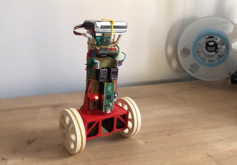
That is what makes the modern self-balancing robot such a perfect teaching machine. It turns abstract math into motion you can see, hear, and panic over in real time. A small two-wheeled robot built from printed parts, a microcontroller, an IMU, and a pair of motors can demonstrate core ideas from classical control, embedded systems, mechanical design, and rapid prototyping all at once. In one memorable Hackaday-featured build, the robot used a 3D-printed frame and wheels, stepper motors, a Raspberry Pi Pico, and an MPU-9250 sensor package to create a compact balancing machine that made control theory feel less like a textbook hostage situation and more like a hands-on breakthrough.
Why self-balancing robots matter
A self-balancing robot is really a rolling version of the classic inverted pendulum problem. Left alone, it falls. Controlled well, it stays upright by constantly measuring tilt and commanding the wheels to move under its center of mass. That sounds simple until you remember the robot must do this continuously, quickly, and with just enough correction to avoid making things worse.
That is the magic of the platform. It is unstable by nature, so it rewards good control design and punishes lazy assumptions. Students and hobbyists do not just learn that feedback exists. They feel what feedback does. A gain set too low makes the robot sluggish. A gain set too high turns it into a caffeinated shopping cart. Poor filtering adds jitter. Bad mechanical alignment turns a promising project into a dramatic floor inspection device.
Universities have used inverted pendulum robots for exactly this reason. They are powerful teaching tools because they connect modeling, stability analysis, sensor calibration, and controller tuning to a physical result that is impossible to ignore. When the robot balances, the theory suddenly stops being theoretical.
How a 3D-printed build changes the learning experience
3D printing gives this kind of project an unfair advantage: speed. Instead of waiting on custom machining or settling for a pile of mismatched brackets, builders can design a chassis in CAD, print a part, test it, dislike it, mutter something impolite, tweak the file, and print again. That cycle is exactly what rapid prototyping is supposed to be. It is faster, cheaper, and far more forgiving than traditional fabrication for small robotics projects.
For a balancing robot, that matters more than it first appears. The geometry of the frame affects the center of gravity. Wheel size changes the dynamics. Mounting height for batteries and boards changes stability. Even cable routing can influence performance if it shifts weight or creates drag. A 3D-printed frame lets the builder experiment with these variables without rebuilding the entire machine from scratch.
It also makes the project more accessible. Students can go from CAD to physical hardware in a short time, which means they can connect design decisions to control behavior almost immediately. That bridge between digital design and physical testing is where many engineering lessons become sticky. You do not forget the center-of-mass lesson after your robot faceplants because you mounted the battery like a tiny rooftop water tank.
The core hardware behind the balancing act
1. The chassis and wheels
The body needs to be stiff enough to avoid flex, light enough to move quickly, and balanced enough to keep the controller from fighting bad mechanics. In many printed designs, wheels are also printed, sometimes with rubber bands, tires, or sleeves added for traction. That combination keeps the cost low while allowing quick redesigns.
2. The motors
Balancing robots commonly use DC gear motors or steppers. The featured 3D-printed build used stepper motors with a DRV8825 driver, which gave the robot precise actuation in a compact package. Other balancing platforms use DC motors with encoders because encoders add another valuable stream of data: how far the robot has moved and how fast it is traveling.
3. The IMU
This is the robot’s inner ear. An IMU typically combines an accelerometer and gyroscope, and often a magnetometer too. The gyroscope tracks angular motion, which is extremely useful for seeing how fast the robot is tipping. The accelerometer senses gravity and helps estimate which direction is down. Together, these sensors let the controller estimate tilt, which is the single number standing between “balanced robot” and “small mechanical tragedy.”
4. The controller
A microcontroller such as a Raspberry Pi Pico, Arduino-class board, or similar embedded platform reads the sensor data and updates the motor commands in a tight loop. Some platforms split responsibilities: a low-level board handles motors and sensors while a second processor handles higher-level logic. That setup is common in more advanced balancing robots because real-time stability is not the kind of job you want delayed by a side quest.
Where control theory enters the chat
The moment the robot starts trying to stay upright, control theory takes the wheel, preferably without overcorrecting. The simplest explanation is that the robot compares where it is to where it wants to be, then uses that error to decide how hard to drive the wheels.
In many beginner and intermediate projects, the first controller is a PID controller. The proportional term reacts to current error. The integral term reacts to accumulated error over time. The derivative term reacts to how quickly the error is changing. Together, they can produce surprisingly effective balancing behavior. PID remains popular because it is intuitive enough to learn, powerful enough to work, and frustrating enough to teach humility.
But balancing robots also reveal the limits of simple intuition. Real systems are noisy. Motors have lag. Chassis flex exists. Sensors drift. Ground friction changes. That is why more advanced projects and academic examples often move into state-space methods, pole placement, or LQR-style thinking. Once you start caring about angle, angular velocity, position, and speed all at the same time, the robot begins to look less like a toy and more like a compact control systems laboratory.
Sensor fusion: because sensors lie in different ways
If you have ever worked with IMUs, you know the accelerometer and gyroscope are like two coworkers who are both useful and both slightly dramatic. The gyroscope responds quickly, but its estimates drift over time. The accelerometer knows where gravity is, but it gets noisy when the robot moves or vibrates. Sensor fusion combines their strengths to produce a better estimate of orientation.
That fusion can come from a complementary filter, a Kalman filter, or an onboard fusion chip that handles the hard work internally. Some boards make this easier by outputting already-fused orientation data, which is great for fast development. Other builders prefer raw sensor data so they can implement and tune the filter themselves. Either approach teaches a valuable lesson: the controller is only as good as the state estimate it receives.
Why encoders and translational motion matter
New builders often focus only on tilt, which makes sense because tilt is the dramatic part. But balancing is not just rotational. The robot must also manage translation. If it starts rolling away while balancing, it may stay upright briefly while making a strong case for being someone else’s problem.
That is where motor encoders become especially helpful. They provide distance and speed information, giving the controller more context. Some balancing algorithms use angle, angle rate, distance, and speed together to generate motor commands. This broader view usually improves stability and makes the robot feel less twitchy and more intentional.
Why this project is such a good teacher
A 3D-printed self-balancing robot does not just teach one subject. It teaches several at once.
Mechanical design
Students learn about stiffness, weight distribution, tolerances, wheel traction, and fastener choices. Suddenly, a CAD file is not decorative. It is a physical argument with gravity.
Embedded programming
The control loop must run predictably and quickly. Timing matters. Data filtering matters. Interrupts matter. Bad code does not just produce ugly output. It produces a robot that wiggles like it is rethinking its life choices.
Modeling and simulation
Tools from university courses and engineering platforms show how a system can be modeled before it is built. That matters because the inverted pendulum is one of the great examples of why simulation and real hardware need each other. The model helps you understand the system. The hardware reminds you that friction, backlash, noise, and reality are undefeated.
Experimental thinking
Perhaps most important, builders learn to test methodically. Change one gain. Try one filter. Move one component. Reprint one bracket. That kind of disciplined iteration is a bigger engineering lesson than any single balancing success.
Specific examples that bring the idea into focus
The Hackaday-highlighted robot is a great example because it packages serious ideas in a build that still feels reachable. A printed body and wheels keep the cost and complexity down. The Raspberry Pi Pico handles the control logic. The MPU-9250 provides motion data. The stepper motors, guided by a PID loop, do the balancing work. In other words, it is not just a robot. It is a neatly packaged demonstration of feedback control, embedded programming, and physical prototyping.
Commercial and educational platforms push the same lesson further. Pololu’s balancing robot family shows how IMUs, encoders, and control boards can be integrated into a cleaner reference design. Arduino and MathWorks have used self-balancing motorcycle projects to teach model-based design and inertial sensing. University courses use inverted pendulum robots to help students connect eigenvalues, stability, and controller tuning to actual machine behavior. Different form factors, same truth: balance is a brutal and brilliant teacher.
The bigger lesson: theory becomes believable when it moves
Control theory can feel abstract because its language is abstract. We talk about poles, states, margins, feedback dynamics, and system response. Useful concepts, yes. Warm and cuddly, not exactly. A self-balancing robot changes that by turning those concepts into motion. It lets you watch stability happen. It lets you hear bad tuning. It lets you diagnose poor filtering from a wobble before you can fully explain the math behind it.
That is why 3D-printed balancing robots are so compelling. They are not just cool builds for the workbench. They are compact demonstrations of how engineering thinking works. You model a system, build a mechanism, sense its behavior, close the loop, test the result, and iterate until the machine behaves. That process is the lesson.
Hands-on experiences: what building one really feels like
Anyone who has spent time with a self-balancing robot knows the experience is equal parts engineering, comedy, and stubborn optimism. The first power-on moment is unforgettable. You place the robot upright, give it a hopeful little release, and watch it immediately collapse like it just heard bad news. That first failure is not discouraging for long, though. In fact, it is weirdly motivating. A balancing robot fails so honestly that it becomes a very good teacher. It does not hide the problem. It falls over and says, in the universal language of physics, “Try again, but smarter.”
The real fun begins once the mechanical design is close and the software loop is alive. Tiny changes start producing wildly different personalities. One gain adjustment makes the robot lazy and slow, like it needs a nap and a motivational speech. Another makes it jitter like it drank four energy drinks and read one chapter of control theory out of spite. You start to realize that tuning is less like flipping a switch and more like negotiating with a machine that is technically obedient but emotionally complicated.
There is also a special satisfaction in seeing 3D-printed parts go from plastic shapes on a build plate to components with real engineering consequences. A bracket that seemed fine in CAD may flex just enough to introduce noise. A wheel that looked great on screen may slip on smooth flooring and ruin your carefully tuned controller. A battery mounted a little too high can make the whole robot feel top-heavy and dramatic. These are the moments when theory stops being a classroom concept and becomes a physical conversation between design and behavior.
Debugging the sensor side brings its own kind of enlightenment. Builders often start by blaming the controller, only to discover the tilt estimate is noisy, the IMU needs calibration, or the sampling loop is inconsistent. Then comes the classic lesson: the robot cannot balance on bad information. Once the sensor readings improve, the whole machine seems to become more reasonable, and that feels almost magical the first time you see it. Of course, it is not magic. It is good estimation. But engineering is full of moments that feel like magic right up until you understand them.
Another memorable part of the experience is how quickly curiosity expands. At first, most people just want the robot to stand up. Then they want it to stay in one place. Then they want it to recover from a shove. Then they want it to drive forward, turn smoothly, or survive uneven flooring without acting like a shopping cart with stage fright. A project that begins as “Can I make it balance?” becomes “Can I make it balance well?” That shift is where deeper learning happens.
Perhaps the most valuable experience of all is learning not to fear iteration. A self-balancing robot almost never works perfectly on the first try, and that is exactly why it is so educational. You print a new part. You lower a battery. You retune a derivative term. You filter the gyro data. You add encoder feedback. You test again. Little by little, the robot improves, and so does the builder. By the time the machine finally balances with confidence, the real achievement is not just that the robot stands. It is that the person who built it now understands, in a very practical way, how mechanical design, sensor quality, and feedback control all depend on each other.
And yes, when it finally balances cleanly for the first time, there is a brief moment of unreasonable pride. You will absolutely think, “I have mastered dynamics.” Then the robot will drift into a chair leg and remind you that engineering always has a sequel.
Conclusion
A 3D-printed self-balancing robot brings control theory to life because it turns elegant equations into messy, fascinating, real-world behavior. It shows how unstable systems can be controlled, how sensor data becomes action, how design choices shape dynamics, and how rapid prototyping accelerates learning. More than that, it makes engineering feel tangible. The robot does not just demonstrate feedback. It performs it in front of you, wobble by wobble, correction by correction, until the theory finally stands on its own two wheels.